Technical Article, February 7th 2022
Rapid Alloy Development for LPBF Using EHLA:
First Investigation Results Indicate Feasibility
Laser Powder Bed Fusion (LPBF) is an important Additive Manufacturing (AM) production process since it contributes to meeting today’s industries’ global requirements of high resource efficiencies, individualized part manufacturing and lightweight constructions, among others. A further significant advantage of the LPBF process characteristics is the possibility to process alloys with beneficial mechanical properties that conventional manufacturing technologies could only hardly or even not process. However, this potential has not been exploited to the fullest so far because the development of alloys that make the most out of LPBF-process characteristics like high cooling rates is time and resource consuming. In this context, the process qualities of Extreme High-Speed Laser Material Deposition (EHLA) like in situ powder supply of individual alloys and LPBF-similar cooling rates present promising prerequisites to use this process to rapidly validate alloys to be developed for LPBF in a resource-efficient way.
How to: Comparison of two fundamentally different AM processes
EHLA and LPBF mainly differ in their powder supply mechanisms and the place of laser energy input (laser spot): In LPBF, the powder is applied globally in a powder layer and the laser spot is focused on the powder layer surface. In EHLA, the powder is applied locally via a powder mass flow supplied through a nozzle and the powder focus is positioned slightly above the deposition surface, approx. 1 mm. Thereby, individual alloys can be conveyed and separately mixed in situ before deposition.
Beneficial mechanical properties and advanced material processability are of special interest for users from industry when it comes to LPBF alloy requirements. Mechanical properties result from the parts’ microstructural properties which, in turn, are significantly influenced by their chemical composition and the cooling rate. For this reason, the Aachen AM-experts identified and investigated the relevant EHLA and LPBF process parameters that influence the cooling rate and, hence, the resulting microstructures in a first step. Additionally, they transferred their findings to manufacturing samples made from high manganese steel X30Mn22. In a final step, they compared the samples’ microstructural properties resulting from the LPBF and EHLA manufacturing process to review their assumptions regarding the process transferability and, thus, the qualification of the EHLA process for alloy development.
Results
Since the intensity of the energy input into the powder material has major impact on the cooling rate, the interaction time between powder material and laser beam as well as the energy input into the material, i.e. laser intensity at laser spot, are calculated and compared for both processes: Taking the parameters laser power (PL) and laser spot diameter (Ø spot) into account, it is found that the intensity in LPBF is almost 14 times higher than in EHLA. However, the interaction time between material and laser beam in LPBF and EHLA differs by approximately factor 10. For this reason, it can be assumed that the effects of the different laser intensities are balanced out and lead to a similar energy input per particles.
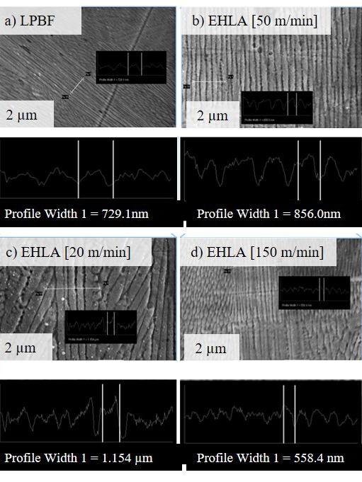
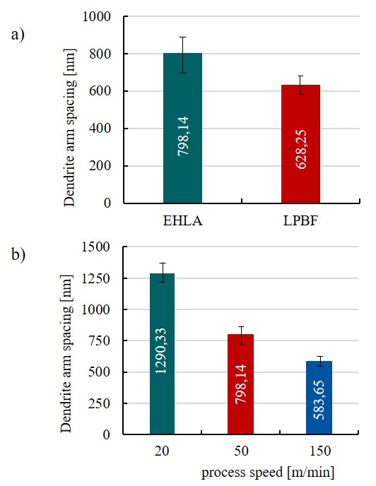
In addition, the researchers determined the influence of the EHLA process speed on the cooling rate by measuring the resulting dendrite arm spacings (DAS). In a second step, these DAS were compared to the DAS found in LPBF processed material. Increasing the EHLA process speed from 50 to 150 m/min, the DAS is reduced from 1.29 µm to 0.58 µm. Therefore, the results indicate that also the cooling rate in EHLA is essentially dependent on the process speed (see image 3 and 4).
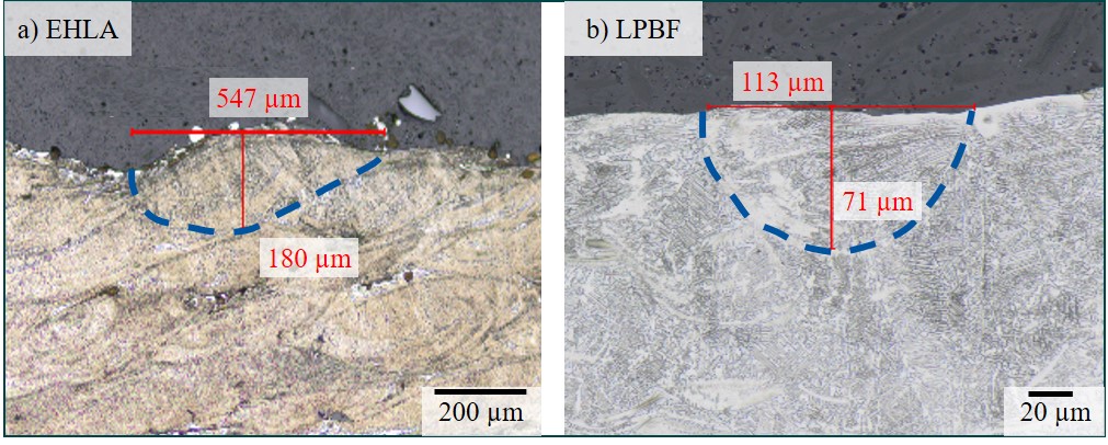
Another value to investigate the processes’ transferability is their resulting energy volume density (𝐸𝑣). It can be used to compare the EHLA and LPBF process characteristics laser power, scanning speed and powder mass flow rate with regard to the thermal balance. The calculated 𝐸𝑣 for LPBF is about 2.3 times greater than the 𝐸𝑣 for EHLA. However, the calculated 𝐸𝑣, LPBF only corresponds to a molten material quantity of a single layer thickness. Since the actual depth of molten material in the LPBF process is 2 – 3 times the layer thickness (see Image 2), the 𝐸𝑣, LPBF has to be adapted accordingly. For this reason, the researchers assume that the heat balance is similar in both processes.
Further investigations on the different melt pool characteristics geometry and size show that the EHLA melt pool geometry measures a 25 times larger area than the one of LPBF – a result from the different laser spot sizes used in both processes. Additionally, the melt pool shapes differ: For EHLA it can be said that the melt pool is rather flat compared to the LPBF melt pool (see image 2). This is mainly due to the form of energy input of the two processes into the material and the heat dissipation from the melt pool into the substrate or the layers below. In EHLA, approximately 80% of the energy is absorbed by the powder particles which then impinge onto the substrate in the melted state. Only about 20% of the energy is absorbed by the substrate and, thus, the substrate itself is only melted to a small extent. This causes a small melt film in EHLA in contrast to a veritable melt pool seen in LPBF, that is 2 – 3 times the LPBF layer thickness. Considering the melt pool depth and width (d/w ratio), the d/w ratio for EHLA is 0.37 and for LPBF it is 0.60. This result reveals different types of welding. In EHLA, heat conduction welding appears whereas in LPBF it is transition welding and eventually deep welding in case of higher energy input. In this context, the Aachen researchers will look into mechanical properties like micro hardness, tensile strength and ductility, to be able to make statements about the effect of these different welding regimes and the resulting consequence for the processes’ transferability.
Fundamentally Different but Promising, However
The microstructure of the manufactured samples is dendritic in both processes and the obtained dendrite arm spacings (DAS) are similar and can further be aligned by adapting process parameters such as process speed in EHLA. Therefore, it can be assumed that the the resulting microstructures and therefore mechanical properties are comparable for EHLA and LPBF.
Further investigations will compare the chemical compositions of the manufactured samples obtained by EHLA and LPBF. The EHLA process parameters like particle velocity and powder mass flow will also be examined with regard to their influence on the resulting samples’ chemical properties. In addition, due to the difference in energy input, the evaporation behavior of various alloys will be investigated and compared.
To sum up, with regard to microstructural properties, the results indicate that EHLA is suitable as an advanced alloy screening and development tool for LPBF.
In the future, a 3D-EHLA system will be used at the DAP Chair to further investigate the use of EHLA as a Rapid Alloy Development tool for LPBF and other AM technologies. In contrast to conventional EHLA, this system can be used to manufacture three-dimensional components. Furthermore, the facility is tailor-made for fast and resource-efficient alloy development: besides the possibility to mix up to eight different alloys simultaneously, it is equipped with extensive process sensors and material analytics to investigate the interaction between laser beam and material and the subsequent material characterization.
This research is funded by the Deutsche Forschungsgemeinschaft (DFG, German Research Foundation) under Germany’s Excellence Strategy – EXC 2023 Internet of Production- 390621612
© RWTH DAP / Irrmischer.
a) EHLA melt pool in light microscope (LOM) micrograph with a magnification of 100x
b) LPBF melt pool in LOM micrograph with a magnification of 500x.
© RWTH DAP.
a) Scanning Electron Microscope (SEM) image of dendritic structure obtained in samples produced with standard
LPBF-process parameters
b) SEM image of dendritic structure obtained in samples produced with standard EHLA process parameters
c) SEM image of dendritic structure obtained in EHLA-samples with a reduced process speed of 20 m/min
d) SEM image of dendritic structure obtained in EHLA-samples with an increased process speed of 150 m/min
© RWTH DAP.
a) Dendrite arm distances in samples produced using EHLA and LPBF standard parameters
b) Dendrite arm distances in samples produced with various process speeds in EHLA.
© RWTH DAP.
Stephan Koss, M. Sc.
RWTH Aachen Chair
Digital Additive Production DAP
Advanced Processes Group
Campus-Boulevard 73
52074 Aachen
Marie Bold, M. Sc.
RWTH Aachen Chair
Digital Additive Production DAP
Group Manager Advanced Materials Group
Campus-Boulevard 73
52074 Aachen
Further News
Dyndrite First to Support New LPBF Open Vector Format (OVF)
Dendryte Press Release, October 31TH, 2022 Dyndrite First to Support New LPBF Open Vector Format (OVF)SEATTLE, WA, Monday October 31, 2022. — Today, Dyndrite™, providers of the GPU-accelerated computation engine used to create next-generation digital manufacturing...
Project IDAM is a complete success: An important milestone in the additive series production of automotive parts
press release, June 22TH, 2022 Project IDAM is a complete success: An important milestone in the additive series production of automotive partsA consortium of 12 project partners has set up two fully automated production lines for the additive series production of...
Open Vector Format Reduces the Size of Multidimensional Manufacturing Data Volumes for Laser Powder Bed Fusion
Press Release, April 25TH, 2022 Open Vector Format Reduces the Size of Multidimensional Manufacturing Data Volumes for Laser Powder Bed FusionStreamlining data volumes while simultaneously increasing data depth of 2D manufacturing data for Laser Powder Bed Fusion...
This picture shows a component that was developed in one of our projects together with Kueppers Solutions GmbH.

